
Four decisions before you choose a gearhead
Published . Evidence reviewed . Calculations are reproducible examples; catalog observations apply only to the named products. Prepared by Micro Gear Motor OEM; send corrections or an engineering inquiry.
1. Calculate the loaded output point
Reduction changes speed and torque together; gearbox efficiency reduces the torque available from a given motor point.
2. Match ratings to the exact model
Published limits vary with configuration. Diameter alone cannot determine permissible torque or shaft loads.
3. Treat efficiency as operating-point data
A catalog maximum is not a guaranteed value at every speed, torque or temperature. Run a sensitivity check before freezing the motor choice.
4. Specify holding separately
Friction-dependent resistance to backdriving is not a guaranteed holding brake. Evaluate the complete drive under its intended conditions.
Method: one steady running point
Use the same loaded motor point for both speed and torque. These equations estimate the output available from that point, assuming a fixed forward efficiency. They do not determine whether the motor can sustain it electrically or thermally. maxon: Gear technology, pp. 72–73
n_out = n_in / i
T_out = T_in × i × η
P_in = T_in[N·m] × 2π × n_in / 60
P_out = P_in × η
P_loss = P_in − P_out
1 gf·cm = 0.0000980665 N·m
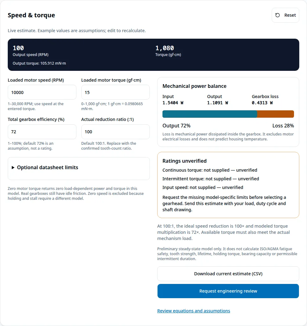
Here i is input revolutions per output revolution, η is efficiency as a fraction, speed n is in RPM and power P is in watts. Example: 10,000 RPM × 15 gf·cm at 100:1 and 72% gives 100 RPM, 1,080 gf·cm (105.912 mN·m), about 1.5404 W input and 0.4313 W gearbox loss.
Scope: forward steady motion only. No automatic ISO 6336/AGMA tooth-strength calculation or ISO 281 bearing-life calculation is performed. Motor copper loss, idle friction, acceleration, shock and ambient thermal resistance need separate analysis. A loss in watts does not predict a temperature rise.
Reproduce the calculator example
Exact ratio, stage count and positioning
Overall reduction is i₁ × i₂ × … × iₙ. The split 4 × 5 × 5 = 100 is a mathematical example, not a qualified tooth design. Stage count follows geometry and load requirements; a nominal ratio does not identify it.
| Assumed exact ratio | Calculated output | Decision consequence |
|---|---|---|
| 98:1 | 102.041 RPM | About 2.04% faster than an assumed 100:1. |
| 100:1 | 100.000 RPM | Baseline calculation. |
| 102:1 | 98.039 RPM | About 1.96% slower than the baseline. |
These ratios illustrate rounding sensitivity, not catalog availability. For open-loop travel, displacement per motor revolution scales with 1/i; request the exact ratio and calibrate the mechanism. Ideal reflected load inertia is J_load/i²; gearbox and rotor inertia remain additional loads. maxon: Gearhead mass inertia
Efficiency sensitivity before motor selection
At a fixed motor point, lower efficiency reduces available output torque and increases modeled gearbox loss. The following values are assumptions for comparison, not measured performance. Manufacturer data explains why the actual efficiency varies with configuration and operating point. FAULHABER: Technical Information — gearheads
| Assumed total efficiency | Output torque | Output speed | Gearbox loss |
|---|---|---|---|
| 60% | 900 gf·cm / 88.260 mN·m | 100 RPM | 0.6162 W |
| 72% (tool example) | 1,080 gf·cm / 105.912 mN·m | 100 RPM | 0.4313 W |
| 85% | 1,275 gf·cm / 125.035 mN·m | 100 RPM | 0.2311 W |
If stage efficiencies are known at compatible operating points, their product gives a first estimate of total efficiency. For example, 0.9³ = 72.9%. That assumption does not quantify grease drag or certify a low-temperature start. Request a curve or measure input/output power on the assembled drive.
A published micro-gearhead benchmark — and its limits
The FAULHABER Series 10/1 sheet shows why one generic “10mm rating” is misleading. The following are selected published entries, reviewed 31 October 2026. This is a reference comparison, not an interchangeable OEM specification. FAULHABER: Series 10/1 & 10/1K datasheet
| Configuration | Continuous / intermittent torque | Maximum efficiency | Exact ratio |
|---|---|---|---|
| 3 stages | 54 / 200 mN·m | 70% | 64:1 |
| 4 stages | 100 / 200 mN·m | 60% | 256:1 |
Both list a recommended continuous input speed of 5,000 RPM. At a force application distance of 5mm from the mounting face, the radial load limit is 1 N for 10/1 and 7 N for ball-bearing 10/1K. Axial limits are 2 N and 5 N respectively. Neither of the ratios above is 100:1; do not import these ratings into a different assembly. The tool’s 10,000 RPM example is not an approved operating point for this benchmark.
For the custom assembly being evaluated here, exact torque ratings, efficiency curve, permissible bearing loads, life, price and availability are unknown until a specific drawing and operating profile are confirmed.
Choose the architecture around the mechanism
Planetary and spur options involve different packaging and performance tradeoffs. The guidance below is a selection starting point; verify the candidate’s curve and drawing. FAULHABER: Gearheads Support
| Direction | Reason to investigate it | Check before committing |
|---|---|---|
| Coaxial planetary | Compact coaxial transmission when torque density matters. | Length, input pinion compatibility, rated duty and loaded backlash. |
| Parallel-axis spur | Alternative packaging with acoustic and current-consumption priorities. | Shaft offset, rated load, reversal error and test conditions. |
| Drive with a holding device | Position must remain controlled when power is removed. | Complete-system holding torque, release behavior and loss-of-power validation. |
Do not assume that a worm stage or high reduction alone provides a guaranteed holding function. Friction, vibration and the motor all affect the complete assembly. maxon: Self-locking or back drivability
Failure risks, cost risks and practical alternatives
The mitigation actions are engineering review recommendations. They are not measured capabilities of an unspecified product. Blocked operation and shaft loading need checks beyond the running-point tool. FAULHABER: Gearheads Support
| Risk | Consequence | Minimum action / alternative |
|---|---|---|
| Stall or impact overload | The running torque estimate misses a transient peak. | Measure the current/load trace; set a verified current limit or consider a torque limiter. |
| Pulley, cam or leadscrew loading | Bearing forces or overhung moments may exceed limits even when torque fits. | Specify force and lever arm; consider an external support bearing. |
| Position reversal or unpowered hold | Backlash or friction variation may defeat the motion requirement. | Measure reversal error; consider output feedback or a validated holding device. |
| Temperature and lubricant mismatch | Available torque and life may change outside the qualified environment. | Test cold starts and sustained operation with the approved lubricant and housing. |
| Custom tooling and qualification cost | A low assumed unit price can conceal nonrecurring cost and schedule risk. | Compare dated quotations including tooling, samples, test scope and delivery terms. |
| Over-specifying an exact ratio | An unnecessary custom design can add development work. | Determine whether calibration or closed-loop control permits an available ratio. |
Three worked screening examples
Hypothetical operating points, not customer validations. All use 100:1 and 72% assumed efficiency. Limits below are invented inputs to demonstrate the screening logic, not product ratings.
Small metering mechanism
Input: 5,000 RPM and 5 gf·cm.
Calculated: 50 RPM, 360 gf·cm (35.304 mN·m).
Without model limits, the result remains unverified. Add startup load, dosing accuracy and duty requirements before selecting a part.
Short-travel lock actuator
Input: 8,000 RPM and 20 gf·cm.
Calculated: 80 RPM, 1,440 gf·cm (141.216 mN·m).
If a supplied continuous limit were 1,200 gf·cm and peak 2,000 gf·cm, continuous torque is exceeded. Being below peak does not approve the pulse duration.
Instrument positioning axis
Input: 12,000 RPM and 10 gf·cm.
Calculated: 120 RPM, 720 gf·cm (70.608 mN·m).
If the supplied input limit were 10,000 RPM, speed is exceeded even if both torque limits fit. Reduce speed, change the ratio or evaluate another model.
Turn the estimate into an OEM specification
Send the current estimate with the information below. Unknown values should remain marked as unknown so the review can identify what needs measurement. Custom ratio availability, MOQ, lead time, pricing and inspection scope require a dated quotation.
| Information | What to provide | What it resolves |
|---|---|---|
| Motor and electrical supply | Loaded speed/torque pair, voltage range, continuous and peak current limits. | Whether the operating point is achievable. |
| Mechanism and load profile | Required output speed, running/startup torque, reversals, shocks and on/rest times. | Continuous versus transient loading and duty. |
| Envelope and shaft | Drawing, mounting features, shaft geometry, forces and force application distance. | Mechanical fit and bearing suitability. |
| Environment and acceptance | Temperature, contamination, life, noise measurement method and backlash under load. | Test conditions and acceptance limits. |
| Commercial and validation scope | Sample/annual volume, exact ratio need, tooling ownership and required inspection records. | A comparable quotation and qualification plan. |
100:1 micro gearbox questions
Calculation & ratio
What does a 100:1 micro gearbox do?
At an exact 100:1 reduction, 10,000 RPM at the input becomes 100 RPM at the output. Torque is multiplied by 100 times the operating efficiency. This describes a running operating point; it does not establish a gearhead torque rating.
Is every gearbox labeled 100:1 exactly 100:1?
Confirm the exact ratio on the supplier drawing or tooth-count specification. A rounded catalog label can differ from the exact reduction. Enter the confirmed value in the calculator, especially for timing, metering or encoder calculations.
Must a 100:1 planetary gearbox have three stages?
No fixed stage count follows from the ratio alone. Overall reduction is the product of stage ratios. A mathematical split such as 4 × 5 × 5 gives 100, but tooth geometry, planet spacing, strength and package dimensions must all be checked before it becomes a physical design.
Which torque and speed should I enter?
Use motor torque and speed from the same loaded operating point at the intended voltage. Do not combine no-load speed with stall torque. The calculator uses magnitudes for steady forward operation and excludes zero-speed holding or stall.
Why is the default efficiency 72%?
It is an illustrative assumption for sensitivity analysis, not a measured value or a universal three-stage rating. Replace it with operating-point data. Catalog maximum efficiency can overestimate performance away from its test point.
Limits & integration
Does a result within the supplied limits mean the design is safe?
It means only that the entered running torque and speed do not exceed the entered limits. Output power, transient loads, bearing forces, temperature, lubrication and life remain unverified. This calculator does not perform an ISO or AGMA strength calculation.
Can I exceed continuous torque for a short movement?
Only within the selected gearhead’s approved intermittent torque, on-time, rest interval and temperature conditions. There is no universal 10-second or 15% duty allowance. A peak number alone does not approve a motion cycle.
Will 100:1 hold a load with the power off?
Ratio alone cannot guarantee holding. Backdrivability depends on the complete motor, gearbox and mechanism. Where loss of holding is consequential, specify a suitable brake or independently validated holding device and test the complete assembly.
Can I mount a pulley or leadscrew directly on the shaft?
Check the exact radial and axial force limits, force application distance and attachment method. A torsional capacity check does not verify bearings. Consider an external bearing arrangement when the shaft loads exceed the gearhead specification.
OEM sourcing
How do I compare planetary and spur options?
Compare the required output point, envelope, bearing loads, backlash under load and noise under a defined test condition. Planetary layouts offer compact coaxial reduction; spur layouts may suit different packaging and acoustic priorities. Obtain model-specific curves rather than ranking by architecture alone.
What are the price, MOQ and lead time?
Public evidence is insufficient to quote a price, MOQ, sample date or production lead time for an unspecified custom assembly. Request a dated quotation identifying the drawing revision, volume, tooling, validation scope and delivery terms.
What should I send for an engineering review?
Send the actual ratio, loaded motor point, load profile, duty cycle, voltage and current limits, shaft drawing, temperature range and expected life. Download the estimate and add any unknowns to the blank RFQ worksheet. Confirm required inspection and qualification documents in the quotation.
Sources, dates and unresolved evidence
Primary sources checked on . Specifications can change; use the revision supplied with your quotation. These references support the principles and named catalog observations, not an assertion that this OEM assembly has been tested to their limits.
- maxon: Gear technology, pp. 72–73
April 2023 edition. Speed/torque conversion and selection principles; not a specification for this OEM page.
- FAULHABER: Series 10/1 & 10/1K datasheet
Edition 2026-07-28, p. 1. Model-specific catalog benchmark; these models do not include an exact 100:1 ratio.
- FAULHABER: Technical Information — gearheads
Gearhead efficiency section (printed p. 117). Maximum efficiency depends on operating point and configuration.
- FAULHABER: Gearheads Support
Application notes on architecture, backlash, bearings, lubrication and blocked operation. Model-specific limits still apply.
- maxon: Gearhead mass inertia
Updated 2024-08-29. Ideal reflected load inertia and the contribution of internal rotating parts.
- maxon: Self-locking or back drivability
Updated 2026-03-26. Distinguishes intrinsic locking from friction-dependent holding of the complete drive.
Evidence boundary: no product-specific dynamometer data, fatigue results, lubricant qualification, acoustic report or bearing-life study is published for the unspecified 100:1 custom assembly on this page. All worked results are calculations, not empirical curves. Obtain the drawing, approved ratings and relevant test report before a production decision. No certification, price advantage or delivery commitment is inferred from the reference suppliers.