
Back to Solutions

Smart Lock and Valve Actuator Gearmotors

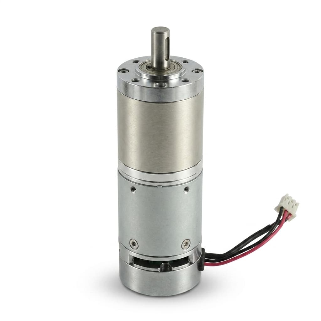
Miniature geared motor assemblies for locks, valves, dampers, and compact rotary actuator systems.

Target Buyer:For device OEMs that need reliable start torque, low noise, and repeatable batch supply.
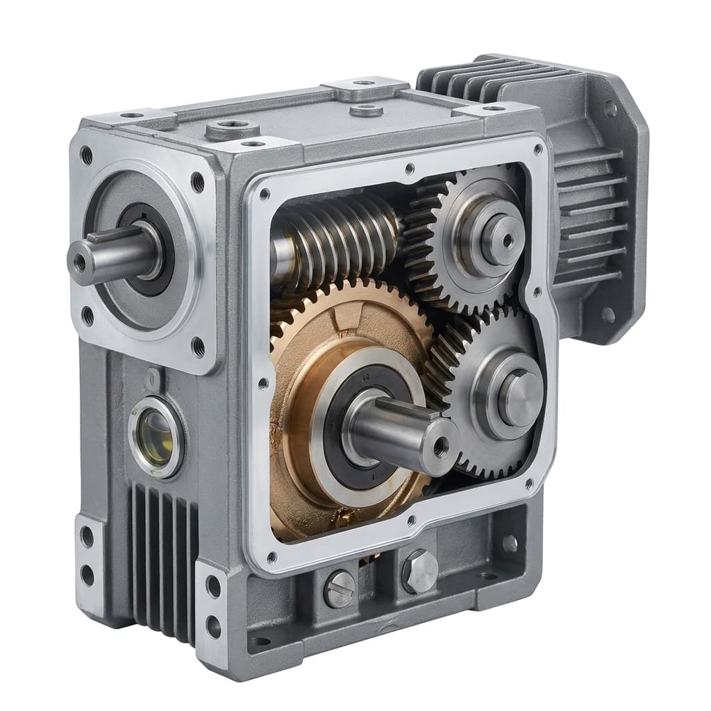
Smart lock and valve actuator right angle gearmotor

Solution Highlights

  • Low current options
  • Quiet gear trains
  • Custom output shafts

Common Use Cases

  • Smart locks
  • Water valves
  • HVAC dampers

Implementation Focus

  • Start torque at low battery voltage
  • Noise inside plastic enclosures
  • Lifetime across start-stop cycles

Application Drive Profile

Recommended Architecture and Validation Focus

Application
Smart lock / valve / damper actuator
Priority
Self-locking, low current, quiet start-stop motion
Architecture
Worm or right-angle gearmotor; N20 spur where back-drive is acceptable
Voltage
3V-12V battery systems
Feedback
Limit switch, Hall, or no feedback by control strategy
Validation
Holding torque, battery current, cold start, noise

Smart locks, water valves, HVAC dampers, cabinet latches, and security modules.

Application Selection Window

Use these inputs to narrow motor architecture, ratio, feedback, and interface choices before sample review.

ParameterSelection GuidanceBuyer Input Needed
Low-voltage start pointMotor winding and ratio should be checked at the lowest battery voltage, not only nominal voltage.Battery chemistry, voltage window, driver current limit, and cutoff behavior.
Output torque and travelValve and lock loads should include seal friction, latch friction, temperature, and aging margin.Required torque, rotation angle, cycle time, stop method, and overload behavior.
Acoustic targetNoise must be checked inside the final plastic or metal enclosure because resonance can dominate.dBA target, measurement distance, enclosure material, and acceptable sound profile.
Shaft and mounting interfaceCustom shaft flats, pins, worm outputs, or flanges can reduce assembly parts and improve repeatability.2D/3D drawing, coupler details, screw pattern, connector, and harness route.

Application Architecture Fit

Match the device constraint to a motor architecture, required buyer input, and proof package before sample release.

RequirementRecommended PathBuyer InputProof to Request
Hold position after power lossUse worm or right-angle gearmotor architecture when anti-backdrive is required.Static load, latch friction, seal force, travel angle, and stop method.Holding torque test, reverse-load check, and output shaft interface drawing.
Reliable low-battery actuationSelect winding, ratio, grease, and motor speed at the lowest battery voltage.Battery chemistry, voltage window, current limit, and low-temperature target.Cold-start loaded current and torque record at the declared voltage.
Low audible noise in plastic housingTune gear material, grease, ratio, and mounting support inside the enclosure.dBA target, enclosure material, measurement distance, and acoustic concern.In-fixture acoustic comparison and pilot-lot noise inspection window.

Application Evidence Pack

Request the right proof set for Smart Lock and Valve Actuator Gearmotors

These buyer-side templates connect the application page to RFQ intake, architecture review, sample validation, and quality release. They make procurement and engineering ask for the same documents at the same approval stage.

Request Application Review

Use-case definition

Application RFQ Scope

Frame Smart Lock and Valve Actuator Gearmotors with the same load, motion, voltage, envelope, interface, project stage, and forecast inputs used by the engineering team.

  • Battery or supply voltage range, including low-voltage cutoff
  • Unlock, latch, valve, or damper torque and travel angle
  • Start torque at low temperature and worst-case friction
Motor architecture fit

Architecture Proof Request

Use application-specific proof requests to decide whether spur, planetary, worm, right-angle, encoder, or custom interface paths should move into sample review.

  • Holding torque test, reverse-load check, and output shaft interface drawing.
  • Cold-start loaded current and torque record at the declared voltage.
  • In-fixture acoustic comparison and pilot-lot noise inspection window.

Sample validation

Application Validation Record

Keep loaded speed, current, torque, temperature, acoustic, duty-cycle, and risk notes comparable before sample approval.

  • Reverse torque and holding-force validation in the buyer latch or valve fixture.
  • Low-voltage start torque and loaded current report.
  • Measured noise comparison with the agreed fixture and distance.

Pilot / repeat order

Pilot Quality Release

Tie the approved application sample to incoming inspection, EOL checks, packaging, labeling, and compliance documents before repeat orders scale.

  • Low-voltage start torque test at specified temperature and load.
  • Loaded current, no-load speed, and output speed inspection windows.
  • Acoustic comparison inside buyer enclosure or representative fixture.

Application Evaluation Matrix

Evaluation MetricTypical RangeBuyer Relevance
Start torque marginBuyer-load dependentPrevents field failures when friction rises at low temperature or low battery.
No-load and loaded currentBattery budget dependentProtects battery life and avoids controller resets during lock or valve movement.
Cycle life targetDevice program definedSeparates short-duration consumer mechanisms from security and utility programs that need long service life.

Validation Risks

Risks to Close Before Pilot Approval

Back-drive or latch creep after shutdown

Use worm gearing, braking geometry, or control stops when the mechanism must hold load.

Evidence: Reverse torque and holding-force validation in the buyer latch or valve fixture.

Cold-start failure at low battery

Validate motor, ratio, grease, and load at worst-case voltage and temperature.

Evidence: Low-voltage start torque and loaded current report.

Acoustic rejection after enclosure assembly

Test the motor inside the final plastic or metal housing before production release.

Evidence: Measured noise comparison with the agreed fixture and distance.

Layered RFQ Intake

Send Enough Detail for a Useful First Reply

Use the three-layer RFQ structure: application, physical parameters, then project stage. The form routes to sales engineering and keeps email and WhatsApp fallbacks available.

Layer 1 - Application

Layer 2 - Physical Parameters

Layer 3 - Project Stage

Source: smart-lock-and-valve-actuators. Attach drawings, test data, or CAD files in the follow-up email thread if they cannot be submitted through this form.

Configuration Options

  • Low-current brushed DC, worm, spur, or planetary gearmotor selection for battery devices.
  • Custom output shaft, flat, pin, gear, or cam interface for lock and valve couplers.
  • Low-noise gear train, grease, and motor speed review for enclosure resonance.
  • Connector, lead length, polarity, and label controls for repeat assembly.

Validation Evidence to Request

  • Low-voltage start torque test at specified temperature and load.
  • Loaded current, no-load speed, and output speed inspection windows.
  • Acoustic comparison inside buyer enclosure or representative fixture.
  • Cycle-life test plan tied to latch, valve, or damper movement profile.

RFQ Preparation Checklist

  1. Battery or supply voltage range, including low-voltage cutoff
  2. Unlock, latch, valve, or damper torque and travel angle
  3. Start torque at low temperature and worst-case friction
  4. Noise target inside the device enclosure
  5. Cycle life, shaft drawing, connector, and forecast volume

Risk and Mitigation

  • Cold-start failure: Validate motor, ratio, grease, and load at the target low temperature.
  • Audible gear noise through plastic housing: Review gear material, ratio, motor speed, grease, and mounting support in the actual enclosure.

Recommended Products

Compact valve actuator drive motor

Buyer FAQ

Can you support custom mounting holes?

Yes. Custom flanges, bosses, hole patterns, and shaft features can be reviewed from drawings.

What information is needed for a smart lock motor quote?

Share battery voltage range, required latch torque, travel angle, cycle target, enclosure limits, shaft drawing, and connector details.

Recommended Decision Path

Continue from this application into matching product families, adjacent use cases, and OEM controls that affect sample approval.

Inquiry Email

[email protected]

Include target torque/speed, quantity, and delivery location.

Instant Chat

+86 188 5797 1991

Routed to sales engineering for RFQ follow-up.