Back to Solutions

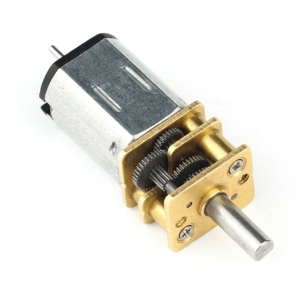
Micro Gear Motors for Industrial Automation

Reliable, continuous-duty geared motors for conveyors, actuators, and automated factory equipment.

Target Buyer:For industrial engineers and procurement teams sourcing robust drives for factory floor automation.
Micro gear motors for industrial automation

Solution Highlights

  • High durability and continuous duty
  • Standardized mounting options
  • Compatible with industrial controllers

Common Use Cases

  • Conveyors
  • Sorting machines
  • Automated testing

Implementation Focus

  • 24/7 reliability
  • Dust and moisture protection (IP rating)
  • Integration with PLCs or motor drives

Application Drive Profile

Recommended Architecture and Validation Focus

Application
Industrial automation / factory mechanism
Priority
Continuous duty, overload margin, closed-loop response
Architecture
Metal planetary or BLDC geared motor
Voltage
12V-24V
Feedback
Encoder or Hall feedback for PLC or driver integration
Validation
Thermal rise, shaft load, gear wear, feedback signal

Conveyors, sorting machines, automated fixtures, compact actuators, and factory modules.

Application Selection Window

Use these inputs to narrow motor architecture, ratio, feedback, and interface choices before sample review.

ParameterSelection GuidanceBuyer Input Needed
Continuous load pointSelect by loaded torque, RPM, ambient temperature, and run schedule rather than short bench tests.Torque, speed, duty cycle, ambient range, airflow, and mounting orientation.
Shaft and bearing loadRoller, pulley, belt, and coupler loads should be checked against the motor shaft and bearing arrangement.Radial load, axial load, pulley diameter, coupler type, and overhung distance.
Electrical interfaceDC, BLDC, encoder, Hall, connector, and wire sequence must match the controller cabinet.Supply voltage, driver type, signal levels, connector, and cable length.
Environment and uptimeDust, moisture, temperature, cleaning, and service interval affect sealing, grease, and inspection scope.IP target, contaminants, ambient profile, service life, and spare part policy.

Application Architecture Fit

Match the device constraint to a motor architecture, required buyer input, and proof package before sample release.

RequirementRecommended PathBuyer InputProof to Request
Continuous or high-cycle dutySelect motor type and ratio from loaded torque, RPM, ambient temperature, and run schedule.Torque, speed, duty cycle, ambient range, airflow, and mounting orientation.Temperature-rise curve and loaded current data at production duty cycle.
Controller compatibilityDefine BLDC, DC, Hall, encoder, connector, polarity, and signal levels before samples.PLC or driver model, supply voltage, IO levels, cable length, and wiring standard.Feedback waveform, wire sequence, direction, and controller compatibility check.
Shock load or bearing loadUse metal planetary gearing and check radial or axial load against shaft support.Pulley diameter, overhung distance, coupler type, radial load, and jam risk.Shaft load review, gear material confirmation, and pilot wear inspection.

Application Evidence Pack

Request the right proof set for Micro Gear Motors for Industrial Automation

These buyer-side templates connect the application page to RFQ intake, architecture review, sample validation, and quality release. They make procurement and engineering ask for the same documents at the same approval stage.

Request Application Review

Use-case definition

Application RFQ Scope

Frame Micro Gear Motors for Industrial Automation with the same load, motion, voltage, envelope, interface, project stage, and forecast inputs used by the engineering team.

  • Continuous torque rating
  • Operating environment (IP rating)
  • Control system interface

Motor architecture fit

Architecture Proof Request

Use application-specific proof requests to decide whether spur, planetary, worm, right-angle, encoder, or custom interface paths should move into sample review.

  • Temperature-rise curve and loaded current data at production duty cycle.
  • Feedback waveform, wire sequence, direction, and controller compatibility check.
  • Shaft load review, gear material confirmation, and pilot wear inspection.

Sample validation

Application Validation Record

Keep loaded speed, current, torque, temperature, acoustic, duty-cycle, and risk notes comparable before sample approval.

  • Loaded temperature-rise report at declared production schedule.
  • Controller compatibility check and feedback waveform record.
  • Mechanical load review and CTQ shaft inspection report.

Pilot / repeat order

Pilot Quality Release

Tie the approved application sample to incoming inspection, EOL checks, packaging, labeling, and compliance documents before repeat orders scale.

  • Loaded current, speed, and temperature rise test at the production duty cycle.
  • Shaft load and coupling review against the buyer mechanical layout.
  • Feedback signal, wiring, direction, and controller compatibility check.

Application Evaluation Matrix

Evaluation MetricTypical RangeBuyer Relevance
Duty cycle ratingIntermittent to continuous by designFactory equipment often fails when a sample motor is selected for speed but not heat and duty cycle.
Radial and axial loadShaft and bearing dependentConveyors, rollers, and test fixtures can overload bearings if belt or coupler load is ignored.
Controller compatibilityDC, BLDC, encoder, or Hall optionsDetermines whether the motor can integrate with PLC, driver, sensor, or closed-loop control logic.

Validation Risks

Risks to Close Before Pilot Approval

Thermal overload during continuous operation

Review load torque, ambient profile, airflow, and duty cycle before pilot approval.

Evidence: Loaded temperature-rise report at declared production schedule.

EMI or signal mismatch with controller cabinet

Confirm connector, wire order, signal levels, shielding, and driver interface early.

Evidence: Controller compatibility check and feedback waveform record.

Shaft or bearing overload from pulley load

Validate radial load, axial load, overhung distance, and coupler geometry.

Evidence: Mechanical load review and CTQ shaft inspection report.

Layered RFQ Intake

Send Enough Detail for a Useful First Reply

Use the three-layer RFQ structure: application, physical parameters, then project stage. The form routes to sales engineering and keeps email and WhatsApp fallbacks available.

Layer 1 - Application

Layer 2 - Physical Parameters

Layer 3 - Project Stage

Source: industrial-automation-drives. Attach drawings, test data, or CAD files in the follow-up email thread if they cannot be submitted through this form.

Configuration Options

  • BLDC or brushed DC gearmotor selection based on duty cycle, control, and cost target.
  • Custom shaft, flange, mounting holes, cable, connector, and labeling for panel or machine assembly.
  • Encoder, Hall, or speed feedback for closed-loop conveyor, fixture, or actuator control.
  • Sealing, grease, and bearing review for dust, moisture, or elevated-temperature environments.

Validation Evidence to Request

  • Loaded current, speed, and temperature rise test at the production duty cycle.
  • Shaft load and coupling review against the buyer mechanical layout.
  • Feedback signal, wiring, direction, and controller compatibility check.
  • Outgoing inspection records for CTQ dimensions and performance windows.

RFQ Preparation Checklist

  1. Continuous torque rating
  2. Operating environment (IP rating)
  3. Control system interface
  4. Shaft load, mounting pattern, and duty schedule
  5. Inspection records, spare part strategy, and batch forecast

Risk and Mitigation

  • Environmental contamination: Specify sealed bearings and appropriate IP-rated enclosures for dust and moisture.
  • Thermal overload in continuous operation: Review load torque, ambient temperature, run schedule, and enclosure airflow before pilot approval.

Recommended Products

Industrial conveyor gearmotor

Buyer FAQ

Do you offer IP65 or IP67 rated motors?

Yes, we can provide custom sealing options for harsh industrial environments.

Can you support controller-specific feedback signals?

Encoder, Hall, connector, wire sequence, and output signal requirements can be reviewed with the target driver or PLC input.

Recommended Decision Path

Continue from this application into matching product families, adjacent use cases, and OEM controls that affect sample approval.

Inquiry Email

[email protected]

Include target torque/speed, quantity, and delivery location.

Instant Chat

+86 188 5797 1991

Routed to sales engineering for RFQ follow-up.