
Back to Products

Hollow-Shaft Micro Gearmotors

Specialized micro gearmotors with a hollow output shaft, allowing cables, fluids, or other shafts to pass directly through the center.

Target Buyer:For advanced mechanical teams designing gimbals, robotic joints, or optical systems requiring wire routing through the axis.
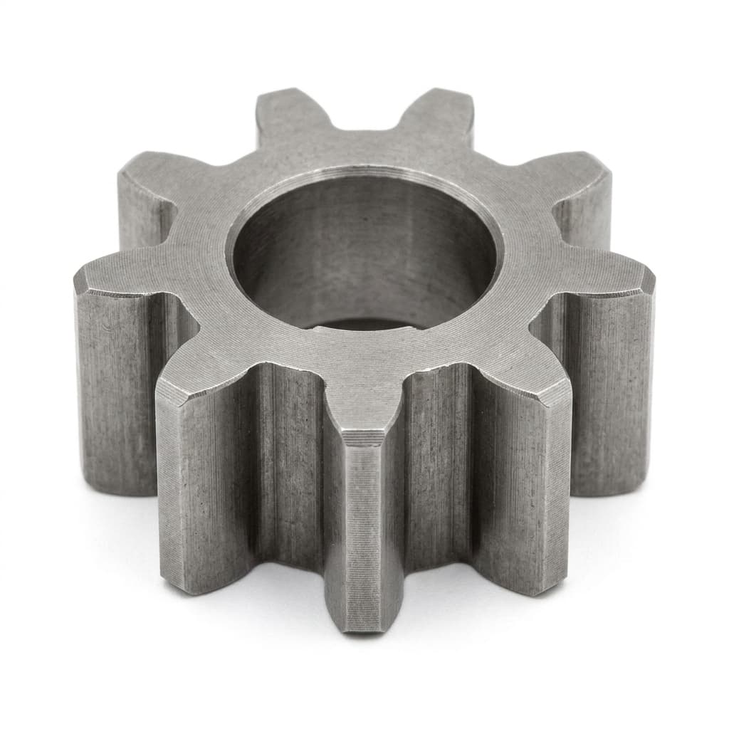
Hollow shaft miniature gear reducer

Capability Highlights

  • Through-hole design
  • Saves space in complex assemblies
  • Custom inner diameters

Typical Applications

  • Gimbals
  • Slip rings
  • Rotary tables

Engineering Focus

  • Inner diameter requirements
  • Bearing selection for large IDs
  • Cable routing clearances

Specification Window

Use these inputs to narrow the product family before sample selection, drawing review, and quotation.

ParameterSelection GuidanceBuyer Input Needed
Through-bore requirementThe hollow shaft ID must leave clearance for cables, tubes, shafts, or slip-ring parts.Required inner diameter, cable bundle size, bend radius, and clearance.
Outer envelopeLarger inner bores affect OD, bearing size, torque density, and gear packaging.Maximum OD, length, mounting plane, and target torque.
Runout and supportConcentricity, bearing support, and output load should be reviewed before sample approval.Runout target, radial/axial load, duty cycle, and positioning need.
Integration routeCable pass-through, connector clearance, and assembly order shape the final motor design.CAD section view, connector size, assembly order, and service access.

Engineering Data Matrix

Family-level ranges for pre-RFQ screening. Final winding, ratio, shaft, connector, and validation values are locked after drawing review.

Model ClassEnvelopeVoltageRatioSpeedTorqueFeedbackDrawing Status
Small hollow-shaft gearmotorCompact through-bore package6-12V reviewCoaxial gearbox reviewLow to medium RPMCable pass-through mechanism loadsEncoder optionalID/OD section drawing by RFQ
Custom ID hollow output driveInner diameter by cable or shaft requirement6-24V reviewApplication-specificApplication-specificBearing and runout dependentOptionalSTEP/IGES section model by project review
Flange-mounted hollow-shaft assemblyCustom flange and through-bore6-24V reviewCustom ratio reviewLow-speed rotary axisGimbal or rotary-table load pointEncoder optionalFlange and bore drawing by RFQ

CAD, Drawing, and Curve Pack

Drawing packs are prepared against the project envelope, so the site does not publish universal CAD downloads that could mislead drop-in selection.

2D outline PDF/DWG3D STEP/IGES envelopeShaft/flange drawing review

Inputs needed before release

  • Target envelope or existing motor drawing
  • Output shaft, flange, mounting, and connector constraints
  • Voltage, loaded speed, torque, duty cycle, quantity, and destination

CAD and drawing packs are released after the project envelope and confidentiality requirements are confirmed.
Performance Review Points

These checks turn a catalog choice into a quoteable sample path with measurable acceptance criteria.

Loaded torque-speed-current point

Buyer input

Target torque, output RPM, voltage, duty cycle, and current limit.

Engineering output

Recommended ratio, winding path, and sample validation point for quotation.

Thermal and duty-cycle margin

Buyer input

Run time, rest time, stall exposure, ambient temperature, and enclosure notes.

Engineering output

Risk note for heat rise, gear wear, lubricant choice, and test scope.

Mechanical interface lock

Buyer input

Shaft drawing, flange hole pattern, cable route, connector, and assembly order.

Engineering output

Drawing review notes before sample build, fixture planning, or batch inspection.

Product Evidence Pack

Request the right engineering files for Hollow-Shaft Micro Gearmotors

These buyer-side templates connect the product family page to the technical library, quality review, and RFQ intake. They help engineering and procurement teams ask for the same files at the same approval stage.

Request This Pack

Product fit

Datasheet and RFQ Baseline

Start Hollow-Shaft Micro Gearmotors screening with the same voltage, torque, speed, ratio, envelope, shaft, quantity, and schedule fields used by the RFQ team.

  • Required inner diameter (ID)
  • Torque and RPM
  • Outer envelope constraints

Mechanical review

CAD and Drawing Release Scope

CAD and drawing packs are released after the project envelope and confidentiality requirements are confirmed.
  • 2D outline PDF/DWG
  • 3D STEP/IGES envelope
  • Shaft/flange drawing review

Sample test

Torque-Speed-Current Validation

Use a shared report format before sample approval so loaded speed, torque, current, case temperature, noise, and pass/fail notes stay comparable.

  • Loaded torque-speed-current point
  • Thermal and duty-cycle margin

Quality gate

Incoming and Release Inspection

Tie the approved sample to inspection checkpoints before pilot builds or repeat orders scale into batch production.

  • Inner bore clearance and cable-wear checks with buyer cable bundle dimensions.
  • Runout, concentricity, and bearing support review.
  • Loaded torque-speed-current validation under the real duty cycle.

Key Evaluation Matrix

MetricTypical RangeWhy It Matters
Inner diameter2mm - 15mmDetermines how many cables or components can pass through the motor axis.

Commercial Scope

RFQ Pricing, Shipping, and Return Baseline

Product-family pages support engineering and sourcing decisions before a custom quotation. They do not operate as cart checkout pages with universal prices, shipping rates, or consumer return handling.

RFQ price basis
Quoted in USD after voltage, ratio, shaft, connector, validation scope, sample quantity, annual volume, destination, and trade terms are reviewed.
Quotation baseline
Commercial review baseline active from 2026-08-06; final price, lead time, and quote validity are controlled by the confirmed quotation or purchase order record.
Export shipping review
Freight cost, Incoterm, destination, packaging, and transit-time assumptions are confirmed during RFQ. This site does not publish a universal cart shipping rate for custom motors.
Custom return scope
Custom samples and production lots are not handled as consumer returns. Replacement, rework, credit, or nonconformance handling follows the confirmed quotation, purchase order, drawing revision, and inspection agreement.
Review Commercial Terms

OEM Customization Options

  • Custom inner diameter, output shaft geometry, flange, and bearing support.
  • Cable pass-through clearance and connector routing review.
  • Coaxial gearbox pairing for gimbals, optical modules, and compact rotary axes.
  • Inspection references for bore size, runout, and mounting geometry.

Validation Evidence to Request

  • Inner bore clearance and cable-wear checks with buyer cable bundle dimensions.
  • Runout, concentricity, and bearing support review.
  • Loaded torque-speed-current validation under the real duty cycle.
  • Mounting and assembly sequence review before freezing drawings.

RFQ Checklist

  1. Required inner diameter (ID)
  2. Torque and RPM
  3. Outer envelope constraints
  4. Life expectancy

Risk Controls

  • Cable friction or wear: Ensure the inner bore is smooth and appropriately sized for the wire bundle.

Product Gallery

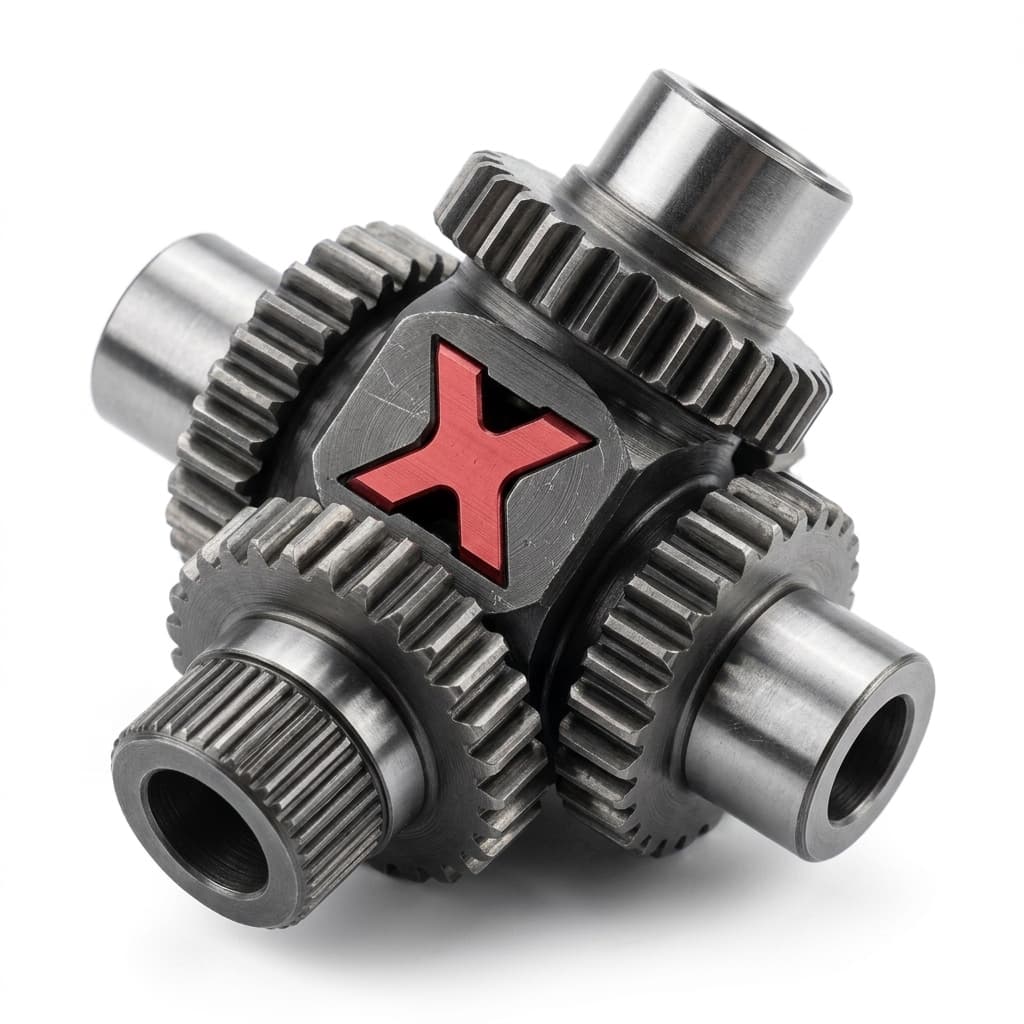
Cross shaft gear assembly for custom output interfaces
Compact hollow shaft motor module
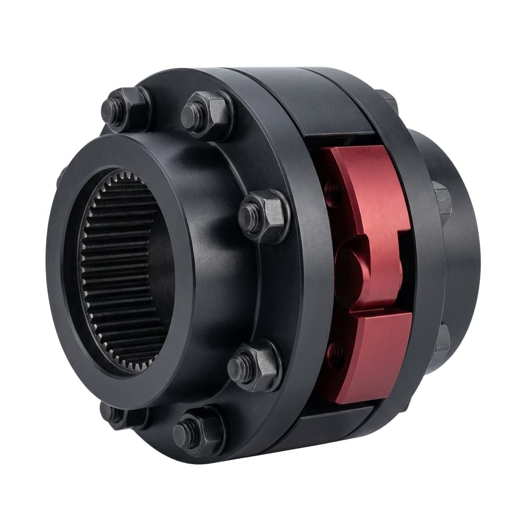
Hollow shaft gearmotor with flange mount

Buyer FAQ

Can you customize the inner diameter?

Yes, we can engineer custom hollow shafts based on your throughput requirements.

Recommended Decision Path

Continue from this product family into adjacent product architectures, application notes, and OEM capability pages.

Request Engineering Review

Share the required envelope, voltage, torque, speed or ratio, shaft interface, harness, feedback, quantity, destination, and validation target. The form keeps email and WhatsApp fallbacks synchronized with the product data you enter.

Product RFQ Intake

Send Selection Data for Engineering Review

Use this form when you need model selection, CAD/drawing review, sample routing, or quotation support for this motor family.

Layer 1 - Product and Application

Layer 2 - Electrical and Mechanical Load

Layer 3 - Stage and Evidence

Attach drawings, CAD files, or test data in the follow-up email thread if they cannot be submitted through this form.