
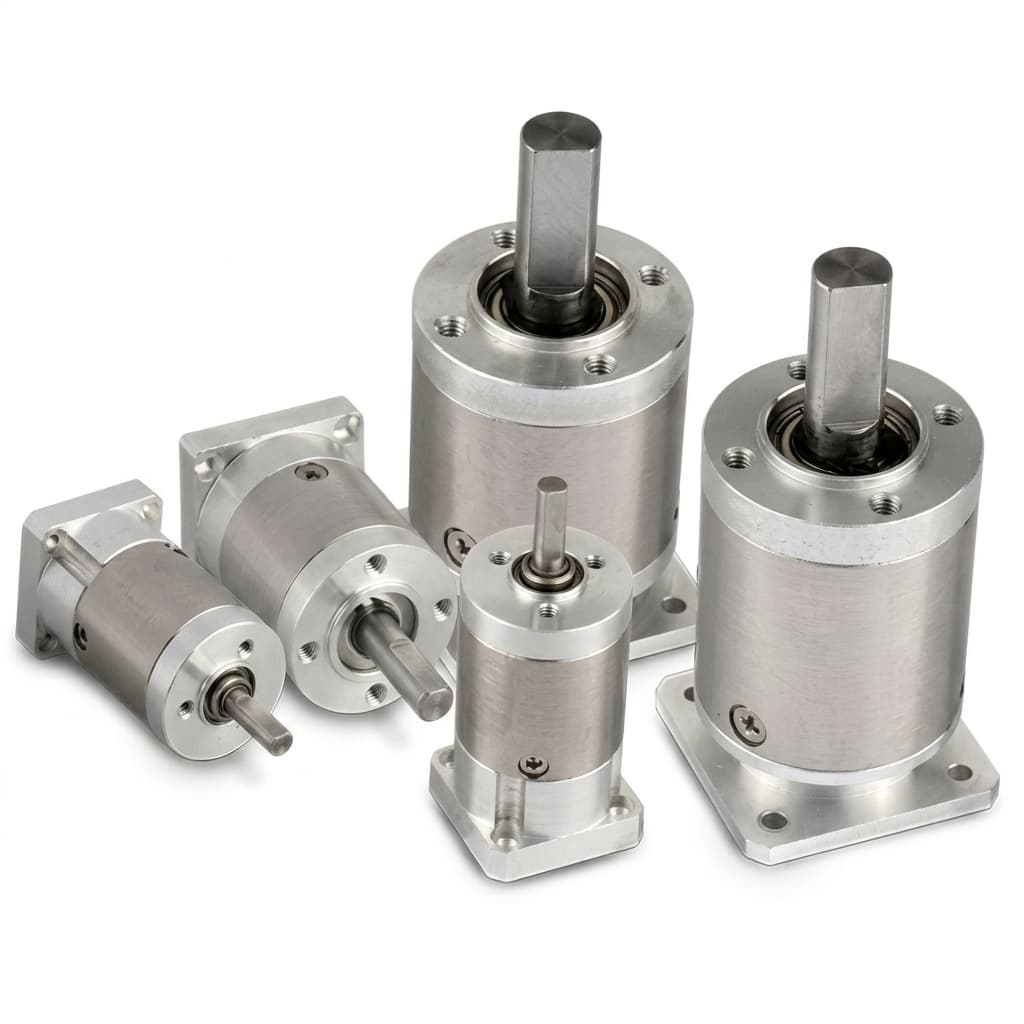
Micro Gear Motor Radial and Axial Load Limits: OEM Sizing & Bearing Guide
Check micro gear motor radial and axial load limits with worked calculations, bearing trade-offs, and an OEM RFQ checklist. Request a review for your assembly.
Micro gear motor radial and axial load limits are specific to the gearbox assembly, load position, output speed, duty cycle, and required life. A torque rating alone cannot establish a permissible shaft load. For an OEM sizing decision, first calculate the forces at the output shaft, then compare them with the supplier's limits at the same load position and operating conditions.
Published and technically reviewed: October 29, 2026. Scope: Global OEM engineering and procurement; SI units; preliminary sizing of miniature geared drives. Worked examples below are hypothetical calculations, not hardware test results or certified product ratings. For medical or other regulated applications, they do not establish device approval.
If your datasheet omits the radial or push/pull thrust limit, request a shaft-load review before selecting a sample. Include the shaft drawing and load cycle. The micro gear motor product portfolio can help identify candidate drive families; frame size is only a starting point.
1. Defining Mechanical Shaft Loads: Radial, Axial, and Moment
Radial load acts perpendicular to the output shaft; axial thrust acts along it. An overhung radial force also creates a bending moment. Portescap's load-selection guide explains why bearing selection, force position, speed, and life must be considered together.
Figure 1. Simplified two-support shaft model, not a product cross-section. The mounting-face datum may differ from the front bearing center.
Radial Load and Bearing Reactions
For the idealized shaft in Figure 1, let x be the distance from the front bearing center to the external load center, and b the center-to-center bearing span. For a single downward radial force Fr, static equilibrium gives:
Bending moment at front bearing section: Mb = Fr × x
Front bearing reaction magnitude:        R1 = Fr × (b + x) / b
Rear bearing reaction magnitude:         R2 = Fr × x / b
R1 acts upward; R2 acts downward in this arrangement. With Fr in N and x in mm, Mb is in N·mm. These reactions exclude internal gear forces, preload, housing flexibility, and other external loads; they are a screening model, not a bearing approval calculation.
Example: For assumed b = 6 mm, x = 9 mm, and Fr = 20 N, R1 = 50 N and R2 = 30 N. A 20 N external force can therefore create a larger front-bearing reaction. Do not compare that internal reaction directly with a catalog's permissible external shaft-load rating.
Axial Push and Pull
Record push thrust and pull thrust separately, including reversals. Lead screws and helical or worm meshes can introduce thrust; shaft retention and bearing preload determine how it is carried. Confirm the force path in the actual gearbox. Two ball bearings do not automatically provide the same capacity in both directions.
Running, Stationary, and Assembly Loads
Ask for running radial/axial limits, stationary-load limits, and press-fit or impact restrictions separately. A published bearing dynamic rating is not the same as a complete gearmotor's permissible shaft force. There is no general 2× or 3× static allowance: shaft strength, bearing contact, retention, and housing constraints can govern independently.
2. Calculating Loads Across Transmission Interfaces
Start with tangential force at the pitch circle:
Ft = 2000 × T / d
T = output torque in N·m; d = pitch diameter in mm; Ft = force in N
This is a torque-to-force conversion, not a universal radial-load formula. Oriental Motor's sizing tutorial distinguishes drive-method coefficients, service factors, and belt tension. Use coefficients only within the transmission supplier's stated method; do not apply a guessed multiplier to every mechanism.
| Transmission interface | Initial force model | Additional input required | OEM sizing action |
|---|---|---|---|
| Flexible coupling | Torque does not establish radial force | Coupling stiffness, offset, angular error, thermal growth | Obtain misalignment reactions; check both shafts and bearings |
| Spur pinion | For a simple external spur mesh: separating force = Ft × tan(pressure angle); transverse resultant = Ft / cos(pressure angle) | Pressure angle, mesh direction, peak torque | Resolve tangential and separating forces at the pinion center |
| Helical pinion | A simple mesh also produces thrust: Fa = Ft × tan(helix angle) | Helix angle, transverse pressure angle, mesh hand and rotation | Calculate transverse resultant and both thrust directions |
| Chain sprocket | Torque relates to the difference in strand tensions | Tight/slack tensions, strand angles, inertia and starts | Sum the strand force vectors; include specified dynamic allowances |
| Timing belt | Torque relates to tight-side minus slack-side tension | Installed tension, working tensions, belt span directions | Sum belt forces; do not omit installation tension |
| Flat belt or O-ring | Transmitted torque does not determine total tension | Friction, wrap angle, stretch and tension variation | Obtain the belt supplier's tension calculation or measure the load |
| Peristaltic pump head | Tube compression force cannot be inferred from torque alone | Tubing, occlusion, pressure, roller geometry, load versus angle | Measure/model radial load over a full cycle; consider a separately supported rotor |
These are simplified force models. Include component weight and process forces where relevant, and evaluate simultaneous force vectors rather than adding every scalar maximum as if they act in the same direction.
Worked Example: A Small Timing-Belt Drive
Assume output torque T = 0.25 N·m, pitch diameter d = 22 mm, and two approximately parallel belt spans pulling toward the driven pulley. Also assume the belt calculation has supplied a working slack-side tension of 10 N; this is an illustrative input, not a recommended installation tension.
Tight-side minus slack-side tension = 2000 × 0.25 / 22 = 22.73 N
Tight-side tension                  = 22.73 + 10 = 32.73 N
Approximate radial shaft force      = 32.73 + 10 = 42.73 N
The sum applies to this assumed span geometry. Resolve vectors for other arrangements. Compare 42.73 N with the actual assembly's permissible external load at the actual load position, speed, and life. If that rating is missing, the result remains unapproved; neither a 0.3 N·m torque rating nor a 16 mm frame proves adequacy. Repeat for acceleration, reversals, and stationary belt tension.
3. Distance Derating: Keep the Reference Datum Consistent
A catalog may measure load position from the mounting face, bearing center, or shaft end. Copy that datum onto the RFQ drawing. A longer overhang increases the bending demand, but the manufacturer's distance-derating curve takes precedence over any generic equation.
For the idealized two-bearing model, an estimate that holds only the front-bearing reaction constant is:
Fallow(x) = Fref × (b + xref) / (b + x)Here x and xref are both measured from the front bearing center. If a drawing instead gives distance s from the mounting face, and the bearing center is a distance a behind that face, use x = a + s and xref = a + sref. Do not substitute face distances without accounting for the offset.
The table below uses assumed b = 6 mm, xref = 5 mm, and Fref = 20 N. It illustrates the arithmetic only; it is not a rating for any frame size or bearing architecture.
| Load distance x from front bearing center (mm) | Front-reaction-limited estimate (N) | Relative to assumed reference |
|---|---|---|
| 5 | 20.00 | 100.0% |
| 8 | 15.71 | 78.6% |
| 10 | 13.75 | 68.8% |
| 12 | 12.22 | 61.1% |
| 16 | 10.00 | 50.0% |
| 20 | 8.46 | 42.3% |
This estimate does not preserve a rear-bearing limit, shaft fatigue limit, or allowable gear misalignment. It also omits combined thrust and internal gear forces. Do not extrapolate it into a product guarantee or use it to increase a published rating for a shorter overhang.
4. Bearing Architecture Comparison: Bushing vs. Ball Bearings
Bearing architecture informs the questions to ask; it cannot supply a universal force rating. Compare these options only after the supplier has confirmed the shaft, retention, housing, lubrication, and duty-cycle requirements.
| Engineering parameter | Sintered sleeve bushing | Front ball bearing + rear bushing | Dual deep-groove ball bearings | Dedicated thrust / angular-contact arrangement |
|---|---|---|---|---|
| Radial load | Verify pressure, sliding speed and wear limit | Front bearing may carry much of the external load | Check reactions at both bearings | Depends on bearing type and arrangement |
| Axial load | Needs a defined thrust surface or separate support | Verify retention and direction of support | Verify fits, shoulders and push/pull limits | Designed around specified thrust directions |
| Clearance and runout | Ask for initial and worn clearance limits | Check both bearing locations | Ask for assembled runout; bearing grade alone is insufficient | Preload and assembly tolerances matter |
| Lubrication | Oil supply and operating conditions affect wear | Check the bushing as well as the ball bearing | Specify lubricant, seals and temperature range | Check lubricant and preload heating |
| Life evidence | Use application wear/endurance testing | Assess bushing wear and rolling fatigue separately | Bearing fatigue calculation plus assembly testing | Include preload, stiffness and combined-load evaluation |
| Cost evidence | Request a quote for the specified assembly | Quote the complete bearing/shaft change | Include assembly and inspection costs | Include preload control and inspection costs |
| Approval basis | Measured wear and function under the load cycle | Verified assembled load path and endurance | Supplier load limits plus test evidence | Supplier analysis and application validation |
ISO 281:2007 concerns rolling-bearing dynamic ratings and rating life, including the basic life associated with 90% reliability. It does not provide a sleeve-bushing life model or guarantee complete gearmotor service life; wear, corrosion, and electrical erosion are outside its stated life scope. Ask the supplier to distinguish a bearing fatigue estimate from measured assembly endurance.
5. Output Shaft and Frame Size: What a Buyer Must Request
There is no defensible N20, 16 mm, or 22 mm load limit based on outside diameter alone. FAULHABER's small gear motor selection overview includes permissible axial and radial shaft loads among the selection parameters, rather than deriving them from size or torque.
Use this evidence matrix for each shortlisted part number:
| Required supplier evidence | What it must identify | Hold the selection if… |
|---|---|---|
| Radial limit | Permissible external force, load position and datum | Only torque or bearing component ratings are given |
| Push/pull thrust limits | Direction, running/stationary condition, retention design | A single unexplained axial number is provided |
| Combined loading | Simultaneous radial/thrust envelope or approved load cases | Separate maxima are treated as simultaneously available |
| Shaft drawing | Diameter, material, flats/grooves, shoulders and load center | Frame size substitutes for the shaft geometry |
| Speed and duty | Output speed, motion cycle, starts, reversals and peaks | A rating at a different operating condition is reused |
| Life basis | Required hours/cycles, reliability basis, test or calculation method | A bearing life number is presented as a gearbox warranty |
| Environment and assembly | Temperature, lubrication, contamination and press-fit restrictions | Installation or exposure conditions are omitted |
For application examples, consult the OEM drive solutions; for validation requirements, review quality and compliance documentation. Request part-specific evidence rather than transferring ratings between product families.
6. How Shaft Deflection Can Damage Internal Gear Stages
Output shaft tilt can change gear alignment and concentrate tooth contact. In many planetary designs the shaft connects to the output carrier; in a spur gearbox it connects to the final driven gear. The actual force path depends on the design.
Figure 2. Qualitative illustration; no universal tilt angle or stress multiplier is implied.
There is no universal shaft-tilt failure angle, contact-stress multiplier, or time-to-failure for all micro gearboxes. Geometry, tooth modifications, material, fit, housing stiffness, and operating load affect the outcome. Inspect contact patterns and bearing seats, and assess shaft deflection together with transmitted torque. A stripped gear alone cannot prove which mechanism caused the failure.
7. Mechanical Troubleshooting: Diagnosing Shaft and Bearing Failures
Use these as hypotheses during lab testing or RMA analysis, not as diagnoses from symptoms alone. Record the original shaft play, loading conditions, current, temperature, and noise before endurance testing.
| Observed symptom | Possible causes | Verification check | Corrective action to evaluate |
|---|---|---|---|
| Radial play grows during testing | Bushing wear, damaged bearing, loose housing fit | Compare play at a defined measuring force; inspect support surfaces | Reduce side load/overhang or revise the support system |
| Final-stage teeth strip | Overload, edge contact, material or lubrication issue | Inspect fracture and contact pattern; compare load/current history | Assess alignment and torque peaks before changing gear material |
| Noise increases under side load | Bearing damage, gear mesh error, contamination | Compare unloaded and loaded noise; inspect bearings and gears | Correct the confirmed load path, lubrication or fit issue |
| Stalls under push thrust | Carrier rubbing, preload change, process obstruction | Apply controlled thrust within approved limits; inspect rubbing marks | Revise thrust support or process load after confirming the cause |
| Shaft fractures near a shoulder | Bending fatigue, overload, notch effect or material defect | Inspect fracture origin and drawing; check actual force history | Reassess shaft geometry, material and external support |
| Axial float exceeds the drawing | Retention issue, tolerance stack or wear | Measure at a specified push/pull force; inspect retention | Correct tolerance and retention design; do not add preload blindly |
Further selection material is available in the technical library. Preserve sample identity and test conditions so a supplier can reproduce the failure investigation.
8. OEM Procurement Checklist: Specifying Shaft Loads in Your RFQ
Include these eight items in the drawing pack and obtain a written supplier response for the exact assembly revision:
- 1. Load geometry: Dimension the radial load center from a named datum, include tolerances, and identify the shaft orientation and attached component weight.
- 2. Radial load cycle: State working and peak forces in N, direction, duration, belt installation tension, and the transmission calculation method.
- 3. Axial load cycle: State continuous and peak push/pull forces separately, including reversals, shocks and assembly press-fit loads.
- 4. Combined-load cases: Provide simultaneous torque, radial force and thrust at output speed; request an approved envelope or written case-by-case assessment.
- 5. Shaft and bearing interface: Provide drawing revision, shaft retention, runout and end-play acceptance limits measured at defined forces; ask the supplier to select a suitable bearing arrangement.
- 6. External support and assembly: Show couplings/support bearings and their alignment tolerances; obtain an approved press-fit procedure that avoids an unintended bearing load path.
- 7. Life and acceptance test: Specify hours or cycles, sample count, reliability objective, and pass/fail limits for wear, play, noise, current and function. Distinguish calculated bearing life from assembly test results.
- 8. Duty, environment and sourcing: Provide starts/reversals, temperature, exposure, lubricant constraints, sample quantity, annual volume, destination and change-control requirements.
9. Frequently Asked Questions
Frequently Asked Questions
10. Request a Part-Specific Shaft-Load Review
Before committing to tooling, send your load case and drawing for an OEM engineering review. Include the eight checklist items above and ask for the rated load position, simultaneous radial/thrust allowance, assembly restrictions, and validation plan for the proposed part number.
Treat bearing upgrades, custom shafts, and outboard supports as design options to assess and quote. Confirm their feasibility, limits, cost, and test evidence for your assembly before accepting a production specification.
Sources & Technical References
Sources checked October 29, 2026. These support the stated principles; they do not certify the hypothetical examples or establish Micro Gear Motor OEM product ratings.
- Portescap — The Impact of Torque, Radial, and Axial Loads on Motor Selection: bearing choice, load position, dynamic thrust direction, and press-fit load paths.
- FAULHABER — Small gear motor: selection parameters, including allowable axial and radial shaft loads. This overview does not provide numerical load limits or deflection thresholds.
- Oriental Motor — Motor Sizing Basics Part 4: How to Calculate Radial Load and Axial Load: transmission forces, belt tension, load position and application coefficients. Its product examples are not ratings for miniature OEM gearboxes.
- ISO — ISO 281:2007, Rolling bearings: Dynamic load ratings and rating life: public scope and reliability basis for rolling-bearing rating life. The public abstract supports the scope discussion here; no claim is made to have validated this assembly against the full standard.
Inquiry Email
Include target torque/speed, quantity, and delivery location.
Instant Chat
WhatsApp Engineering Support
Routed to sales engineering for RFQ follow-up.
Author

Categories
More Posts
BLDC vs Brushed Micro Gear Motors: OEM TCO Guide
A financial and engineering comparison between Brushless (BLDC) and Brushed DC gear motors, analyzing lifespan, maintenance, and electronic integration costs.

How to Choose the Right Micro Gear Motor: DC Spur vs Planetary vs Worm
An advanced engineering guide to evaluating micro gear motor topologies, comparing torque density, backlash, efficiency, and material sciences for OEM integration.
OEM Micro Gear Motor Quality Control: 5 Factory Gates
A practical overview of incoming inspection, in-process checks, end-of-line testing, and traceability controls for OEM micro gear motor programs.