
Light running load
Input: 400 gf·cm; continuous / peak: unknown / unknown.
108.8 RPM · 319.8 mA
About 109 RPM and 320 mA is a preliminary candidate point. Request missing gearhead ratings and a loaded thermal test; it is not a released design.
Estimate a loaded operating point, check entered gearhead limits, then use model-specific evidence to prepare your OEM specification.
Request exact-model reviewLive estimate · illustrative inputs · ratings unknown
Illustrative 6 V — hypothetical, not a product specification
Next step: Request exact-model motor curves, continuous and peak gearhead ratings, and thermal data. Validate startup, supply sag and the full duty cycle on samples before release.
Preliminary fixed-voltage estimate using a linear motor curve and constant gear efficiency. No temperature, lifetime, tooth stress, holding brake, startup or driver-current-limit model. Values are not a continuous-duty approval.
Ratio alone does not specify speed, current or continuous torque. Match the required torque and speed together.
A published finished-gearmotor curve already includes its reduction. The calculator requires motor-only values before gearing.
Pololu #1101 — 100:1 HP 6 V · Model-input distinction explained below.
A torque comparison is only one check. Thermal limits require motor-specific data and the actual operating cycle.
| Question | Known on this page | Still required |
|---|---|---|
| Does the arithmetic close? | Deterministic fixed-voltage estimate | Motor curve measurements at the same voltage |
| Is the load within a gearhead rating? | Comparison with values you enter | Exact-model ratings and their conditions |
| Can it run continuously? | Not established | Temperature-rise and full-duty-cycle qualification |
| Will it meet cost and delivery targets? | Not established | Written quotation and sample plan |
This is a transparent screening model for a permanent-magnet brushed DC motor at a fixed terminal voltage. It uses a linear speed–torque curve, a linear current–torque approximation and a constant assumed gear efficiency. The formulas below define the implementation; they do not replace a measured assembly curve.
η = gear efficiency / 100; r = actual reduction ratio
T_motor = T_load / (r × η)
x = T_motor / T_stall; n_out = n₀ × (1 − x) / r
I = I₀ + (I_stall − I₀) × x
P_out = T_load(N·m) × 2π × n_out / 60
P_in = V × I(A); P_motor = P_out / η
1 gf·cm = 0.0000980665 N·m = 0.0980665 mN·m
At x ≥ 1, running speed and power are set to zero and current reaches the entered stall value, assuming an unrestricted supply. The displayed stall ceiling is an extrapolation, not measured static torque. Zero external load is supported, but a real gearbox still has idle losses that a constant-efficiency model omits. At and near zero speed, use measured data instead.
| Included | Not included | Practical consequence |
|---|---|---|
| Voltage × current and shaft power | Driver losses, PWM ripple, battery sag | Check supply and driver at startup |
| Linear steady running point | Acceleration, inertia, jams, reversals | Size transient loads separately |
| Entered torque-limit comparison | Gear geometry, tooth stress, fatigue life | Request gearhead ratings and supporting report |
| Estimated motor and gear losses | Ambient, thermal resistance, cooling, winding temperature | No continuous-duty approval |
These are published figures for three identified Pololu assemblies at 6 V, checked on 31 October 2026. They are useful reference points, not specifications for Micro Gear Motor OEM products. Their output figures must not be entered as bare motor data in the tool.
| Exact Pololu model | Actual ratio | No-load output | No-load current | Extrapolated output stall torque / current |
|---|---|---|---|---|
| #1101 HP, precious metal brushes | 100.37:1 | 310 RPM | 100 mA | 1.7 kg·cm / 1.6 A |
| #992 LP, precious metal brushes | 100.37:1 | 130 RPM | 40 mA | 0.74 kg·cm / 0.36 A |
| #3065 HPCB, carbon brushes | 100.37:1 | 330 RPM | 150 mA | 1.6 kg·cm / 1.5 A |
Pololu #1101 — 100:1 HP 6 VPololu #992 — 100:1 LP 6 VPololu #3065 — 100:1 HPCB 6 V
Stall entries are manufacturer extrapolations and are not continuous ratings. The difference between 130 and 330 RPM at the same ratio illustrates why winding and motor selection must precede any generic “100:1” performance claim.
Using an illustrative 13,000 RPM motor, exactly 100:1 gives 130 RPM before load; 100.37:1 gives about 129.5 RPM. This small ratio difference cannot explain the larger winding differences above. Use the actual ratio for speed and encoder conversions.
| Assumed gear efficiency | Loaded output RPM | Motor current | Interpretation |
|---|---|---|---|
| 50% | 100.3 | 419.7 mA | Sensitivity only; no measured efficiency claim |
| 70% | 108.8 | 319.8 mA | Sensitivity only; no measured efficiency claim |
| 85% | 112.5 | 275.7 mA | Sensitivity only; no measured efficiency claim |
The motor stall ceiling and gearhead allowable torque answer different questions. A large motor can overload a small gear train. An entered continuous rating is a condition-specific comparison threshold; a peak rating needs an allowed duration and repetition pattern. Neither creates permission to operate at stall.
ISO 6336-3:2019 — Tooth bending strength describes tooth bending strength calculation. This tool does not know tooth geometry, material fatigue data or load factors, so it does not calculate ISO 6336 stress or certify tooth strength.
Estimated watts of loss are a heat input, not a winding temperature. A thermal assessment needs ambient temperature, mounting, motor thermal parameters and the load cycle. maxon’s I²t explanation explicitly uses nominal motor current and a winding thermal time constant. This tool has neither. maxon — I²t limitation and winding protection
For short moves, record startup current and repetition rate as well as on-time. For long runs, verify temperature stabilization. Do not infer “24/7 safe” from a low percentage of stall current or from a shaft-power number. Selection by power alone can also miss the required torque and speed. maxon — Assigned power rating (2024-08-29)
| Choice | What to compare | Evidence to request |
|---|---|---|
| Offset spur vs coaxial planetary | Envelope, shaft location, loaded torque, backlash, assembly cost | Drawing and exact-model curves; avoid rating by architecture alone |
| Plain support vs rolling bearings | Radial/axial load and overhang at the application | Allowable loads with distances and life conditions |
| D-flat, round or threaded shaft | Hub fit, retention, runout, bending and axial reaction | Controlled shaft and mating-part drawings |
| Metal gears and lubrication | Material, heat treatment, temperature compatibility and wear | Material declaration and relevant qualification record |
Use the encoder’s declared counting convention. If a hypothetical encoder delivers 12 decoded counts per motor revolution, an exact 100:1 ratio gives 1,200 counts per output revolution and 0.3° per count. If “12” instead denotes electrical cycles before quadrature decoding, the count calculation changes. This arithmetic is resolution, not positioning accuracy.
All cases use the same illustrative 6 V motor as the tool, 100:1 and 70% assumed efficiency. The 800/1,500 gf·cm limits in cases 2 and 3 are invented test inputs, not product ratings. These are calculations, not customer trials or factory measurements.
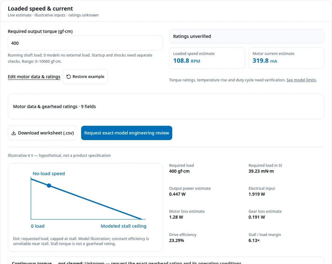
Input: 400 gf·cm; continuous / peak: unknown / unknown.
108.8 RPM · 319.8 mA
About 109 RPM and 320 mA is a preliminary candidate point. Request missing gearhead ratings and a loaded thermal test; it is not a released design.
Input: 1100 gf·cm; continuous / peak: 800 / 1500.
71.6 RPM · 756.9 mA
About 72 RPM does not make this acceptable for continuous duty. An invented 800 gf·cm continuous limit is exceeded; choose another gearhead or reduce load. Peak duration is still unknown.
Input: 3000 gf·cm; continuous / peak: 800 / 1500.
0 RPM · 1,600 mA
The requested load exceeds the modeled 2,450 gf·cm stall ceiling. Predicted running speed and power are zero; redesign and add jam protection.
| Risk | Consequence | Mitigation / alternative |
|---|---|---|
| Using example values as ratings | Wrong motor or unsafe duty assumption | Replace inputs with identified motor data; require sample qualification |
| Using stall torque as working torque | No running speed; high current and damage risk | Size the loaded point; use current limiting and jam detection |
| Power-off holding by ratio alone | Uncontrolled movement of a suspended load | Use an independently rated brake or holding mechanism and validate power loss |
| Radial/thrust load or reversal mismatch | Wear, shaft deflection or positioning error | Add external bearings, thrust support or output feedback as required |
| Comparing unit price alone | Tooling, encoder, test and rework costs omitted | Quote a common specification and acceptance plan; consider a standard assembly |
Application screening recommendations are engineering synthesis from the disclosed model and requested qualification steps. No numerical probability of failure, service life or acoustic limit is established for an unspecified OEM assembly.
Divide bare motor speed by the actual ratio, then account for load. There is no universal RPM. The exact Pololu 6 V assemblies in the comparison table list different no-load speeds even though each is labeled 100:1.
No. It requires bare motor speed and stall torque before the gearbox. Finished output data already includes gearing. Applying the ratio again would double-count reduction. Request motor-only curves, or use the manufacturer’s finished assembly curve directly.
The defaults and both presets are hypothetical examples. They are not catalog specifications or tested OEM products. Continuous and peak ratings start blank and remain unverified until you enter exact-model data.
No. Every motor curve parameter must correspond to the stated voltage and winding. Voltage is used for electrical power; it does not rescale speed, stall torque or current automatically. Replace all related motor data together.
No. It compares a steady running load with entered torque limits. It has no thermal time constants, ambient temperature, motor continuous current rating or transient load profile. It cannot prescribe safe on-time, cooldown or lifetime.
Range validation is insufficient for a motor curve. The tool also rejects inputs that predict motor mechanical power greater than electrical input anywhere along the linear torque curve. Check units and whether you have mixed bare motor and gearbox output data.
The result shows zero running speed and power, with a separate extrapolated stall ceiling. Required torque is not presented as achievable delivered torque. Constant gear efficiency is unreliable near zero speed; stall figures are not gearhead ratings.
No material label establishes an allowable load. Tooth geometry, material condition, supports, impact loads and fatigue requirements must be evaluated for the exact assembly. Ask for continuous and peak gearhead ratings and jam protection requirements.
Do not use the ratio label as a holding guarantee. For a suspended or otherwise hazardous load, specify an independently rated holding solution and verify power-loss behavior. This calculator does not evaluate static holding or backdriving.
No. Convert counts using the actual ratio and the encoder’s stated decoding convention. Output backlash, compliance and missed counts remain separate errors. Specify output accuracy and reversal behavior, not just counts per revolution.
Compare dimensioned drawings, loaded operating points, documented torque ratings, bearing loads, backlash, noise test conditions and total qualification cost. Architecture alone does not establish which assembly is stronger, quieter or cheaper.
They are not established for an unspecified custom assembly on this page. Request a written quotation with quantity, shaft and encoder options, documentation requirements and acceptance tests. Confirm compliance documents for the exact product and shipment.
By Micro Gear Motor OEM · First recorded · Evidence reviewed · Preliminary sizing; exact-model qualification required
Primary sources checked on 31 October 2026. Product numbers are exact-model published benchmarks, not independent tests. The maxon articles explain selection and protection principles; the ISO listing identifies a method, not compliance of this page or a product.
Exact-model ratio, output no-load figures and extrapolated stall data. Applies to this Pololu assembly only.
A different winding with the same nominal ratio; demonstrates why ratio alone cannot select speed or current.
Carbon-brush model benchmark; not an interchangeable rating for a custom OEM motor.
Selection must account for both torque and speed. Power rating definitions differ by manufacturer.
Thermal protection depends on configured motor nominal current and winding thermal time constant; a current fraction alone is insufficient.
Defines a gear-strength calculation method. This tool does not implement it and makes no ISO certification claim.
Evidence not established here: an exact OEM part number and measured curve, continuous thermal capability, gear fatigue life, static holding torque, noise, material certificates, calibration records, price, stock or delivery promises. Request assembly-specific documents and a sample validation plan before purchase or production release.
Share the worksheet and load profile to discuss a suitable motor, gearhead and qualification plan.